 RSS
RSS Twitter
 Facebook
Showing posts with label COMPUTER NETWORKS-I Chapter I. Show all posts
COMPUTER NETWORKS-I × COMPUTER NETWORKS-I Chapter I
• ATM is a high-speed switching
network architecture
• ATM can be used to carry data,
voice, and video
– separately or simultaneously
over same network path
• ATM has a robust quality of
service (QoS)
– can provide seamless
interconnectivity between LAN’s and WAN’s
– supports a wide range of data
rates:
• 25 to 155 Mbps over copper
• 100 to 622 Mbps and higher over
fiber
• common implementation is
155-Mbps ATM
• ATM is specified via a
three-layer reference model:
• Physical layer (OSIs physical
layer)
• ATM layer (generally OSIs data
link layer)
• ATM adaptation layer (AAL)
(generally OSIs higher-level layers (transport,
session, and application)
• Physical layer (2 sublayers)
– Physical medium PM (lower
sublayer)
• definition for the medium
• the bit-timing capabilities.
– Transmission convergence (TC)
(upper sublayer)
• makes sure that valid cells are being created and
transmitted
• involves breaking off
individual cells from the data stream of the
higher layer (the ATM layer)
• checking the cell’s header
• Encoding the bit values
• ATM layer
– service-independent layer
– creates cell headers and
trailers
– defines virtual channels and
paths and gives them unique identifiers
– cells are multiplexed or
demultiplexed.
– ATM layer creates the cells and
uses the physical layer to transmit them.
• ATM adaptation layer (AAL) (2
sublayers)
– Segmentation and reassembly SAR
(lower sublayer)
• packages variable size packets
into fixed-size cells at the
transmitting end
• repackages the cells at the
receiving end
• responsible for finding and
dealing with cells that are out of order
or lost
– convergence sublayer CS (upper
sublayer)
• provides the interface for the
various services (e.g. data, voice, and
video).
• users connect to CS through
service access points
• (SAPs).
• ATM cells are always 53 bytes
long
• partitioned into
– 5 byte header è
contains
addressing information
– 48 byte payload è
contains
user data
• ATM virtual connections consist
of either
– permanent or switched virtual
circuits
– that logically connect source
and destination sites
– Virtual circuits are identified
by specific virtual channel identifiers (VCIs).
• A collection of virtual
channels that all have the same endpoints is called a virtual
path connection (VPC)
• VPCs are specified by virtual
path identifiers (VPIs)
• Virtual connections established
– VCI and VPI assignments are
made dynamically by ATM end nodes and
switches at the time data are to
be transmitted
– VCI is not of interest to e.g.
public switches they would only use the VPI
ATM LAN
• Local area network emulation
(LANE) interface
– can provide a service interface
for the network layer that functions exactly
as the same as Ethernet/802.3 and token ring
– LANs with this interface –
Emulated LANs (ELAN)
• involve special client/server
processes that enables MAC-to-ATM address resolution
• support connectionless nature of local area
networks
COMPUTER NETWORKS-I × COMPUTER NETWORKS-I Chapter I
• First–
Typified by CSMA/CD and token
ring
– Provided terminal to host and
client server
– Moderate data rates
• Second
– Typified by FDDI
– Needed for backbone LANs
– Support of high performance
workstations
• Third
– Typified by ATM
– Provide the aggregate
throughput and real time support for multimedia applications
COMPUTER NETWORKS-I × COMPUTER NETWORKS-I Chapter I
• Ad hoc network: IEEE 802.11
stations can dynamically form network without AP
• Applications:
– “laptop” meeting in conference
room, car
– interconnection of “personal”
devices
– battlefield
• IETF MANET (Mobile Ad hoc
Networks) working group
COMPUTER NETWORKS-I × COMPUTER NETWORKS-I Chapter I
• “dominant” LAN technology:
• cheap $20 for 100Mbs!
• first wildey used LAN
technology
• Simpler, cheaper than token
LANs and ATM
• Kept up with speed race: 10, 100, 1000 Mbps
COMPUTER NETWORKS-I × COMPUTER NETWORKS-I Chapter I
Frame Relay is a way of sending
information over a WAN by dividing data into packets
It operates at the Physical
and Data Link layers of the OSI reference model
It relies on upper-layer
protocols such as TCP for error correction
Frame Relay is a switched data
link-layer protocol that handles multiple virtual circuits using (HDLC) encapsulation
Frame Relay interface can be
either a carrier-provided public network or a network of privately owned
equipment, serving a single enterprise
Frame Relay –benefits
Reduced internetworking
costs
Statistically multiplexed
traffic from multiple sources over private backbone
networks can reduce the number of
circuits and corresponding cost of bandwidth
Lower Equipment Costs
Lower cost than dedicated leased lines
Increased performance &
reduced network complexity
Reduces the amount of processing
(as compared to X.25)
Efficiently utilizing high
speed digital transmission lines, frame relay can improve performance and
response times of applications.
Increased interoperability
via international standards
Frame relay can be implemented
over existing technology
Access devices often require
only software changes or simple hardware modifications to support the interface
standard
Existing packet switching
equipment and T1/E1 multiplexers often can be upgraded to support frame relay
over existing backbone networks.
Frame Relay
overwiew
Packet Switched
Uses Virtual Circuits (Connection
Oriented Service)
Logical connection created
between two (DTE) devices across a Frame Relay packet-switched network (PSN)
COMPUTER NETWORKS-I × COMPUTER NETWORKS-I Chapter I
Internet
• internetwork – interconnection
of networks – also called an “internet”
• Subnetwork – a constituent of
an internet
• Intermediate system – a device
used to connect two networks allowing hosts of
the networks to correspond with
each other
Bridge
Routers
• Internet is an example of an
internetwork.
• internet : collection of
networks interconnected by router and/or bridges
• The Internet
• The global collection of
thousands of individual machines and networks
• Intranet
• Corporate internet operating
within the organization
• Uses Internet (TCP/IP and http)
technology to deliver documents and resources
• End System (ES)
• Device attached to one of the
networks of an internet
• Supports end-user applications
or services
• ES sometimes called DTE
• Intermediate System (IS)
• Device used to connect two
networks
• Permits communication between
end systems attached to different networks
• Examples: Routers and Bridges
• Bridge
– IS used to connect two LANs
using similar LAN protocols
– Address filter passing on
packets to the required network only
– OSI layer 2 (Data Link)
• Router
– Connects two (possibly
dissimilar) networks
– Uses internet protocol present
in each router and end system
– OSI Layer 3 (Network)
X.25
– First public data network
– Connection number used for data
transfer of packets
– data packets contain 3 byte
header and upto 128 bytes of data
– X.25 replaced by Frame Relay
COMPUTER NETWORKS-I × COMPUTER NETWORKS-I Chapter I
A service is specified by a set
of primitives available to a user process to access the
service. These primitives tell
the service to perform some action or report on an action taken by a peer
entity. The set of primitives available depends on the nature of the service being
provided. The primitives for connection oriented are different from the connectionless
service. The five different service primitives for implementing a simple
connection oriented service
Listen: The server
executes LISTEN to indicate that it is prepared to accept the incoming connection.
The server process is blocked until a request for connection appears
Connect: the client
process executes a CONNECT call to establish the connection with the server.
Specify the address too. When the server receives this packet it unblocks the
server and sends back the acknowledgement and this releases the client. At this
point the client and server both are running. The connection established.
Receive: the server
executes RECEIVE to prepare the first request. This call blocks the server.
Send: the client
executes SEND to transmit its request followed by the execution of receive to
get the reply. If the client has additional requests it makes now
Disconnect: The client use
DISCONNECT to end the connection. The server also issues a acknowledgement to
terminate the connection it send the disconnect.
The following figure shows the relationship between
the service and the protocol

A service is the set of primitives or operations
where as protocol are the rules.
COMPUTER NETWORKS-I × COMPUTER NETWORKS-I Chapter I

• Not a network architecture,
because it does not specify the exact services and
protocols to be used in each
layer, it just formally defines and codifies the concept
of layered network architecture
• Each layer describe what
happens at each stage in the processing of data for
transmission
• Layers help to reduce
complexity
• Each layer relies on the next
lower layer to perform more primitive functions
• Each layer provides services to
the next higher layer
• Changes in one layer should not
require changes in other layers
The functions of
different layers
Physical
• responsible for transmitting
raw bits over a communication path
• concerned with issues such as
-mechanical interfaces, e.g.
design of a network connector
-electrical interfaces, e.g.
voltage level of bits
-procedural interfaces, e.g.
whether transmission may
proceed simultaneously in both
directions
Data Link
• Responsible for the transfer of
data between the ends of a physical link
• Provides for error detection,
"framing", and flow control
• Resolves problems due to
damaged, lost, or duplicate frames
• Formatted messages are referred
to as frames rather than packets
Network
• Responsible for the source to
destination routing
• Addresses and resolves all
inherent problems related to the transmission of data
between heterogeneous networks
• Formatted messages are referred
to as packets
• In broadcast networks the
network layer is often thin or nonexistent, because of
easy to solve routing problems
• Sometimes no need for a network
layer if using point-to-point link
Transport
• Provides for error-free
delivery of data
• Accepts data from the session
layer and splits data into smaller packets if
necessary
• passes these packets to the
network layer, and ensures that packets arrive in
sequence, with no losses or
duplications, at their destination
Session
• Provides for coordination
between communicating processes between nodes.
• Manages dialog control (e.g.
Can allow traffic to go in both direction at the same
time, or in only one direction at
time.)
• Responsible for synchronizing
the flow of data, and reestablishing a connection
in the event a failure occurs.
Presentation
• Provides for data formats, and
code conversions
• Concerned with syntax and
semantics of data being transmitted
• Encodes messages in a form that
is suitable for electronic transmission
• Data compression and encryption
is done at this layer
Application
• Consists of protocols that
define specific user-oriented applications such as email,
file transfer, and virtual terminal
Notes
Differences between a computer
network (CN) and a distributed system(DS)
• CN collection of computers
connected by single technology
• DS collection independent
computers appears as one coherent system
• Middleware responsible for the
DS
• WWW is the example of DS
• DS software system built on top
of network
The two services a network offers
Connection
oriented
• A connection is established
between ES’s (end System) that is used for duration
of call
Call setup
Data transfer
Call termination
E.g: Virtual circuits at this
layer
• IS’s ( intermediate system)
connect two or more networks
IS appear as ES to each network
Logical connection set up between
ESs
-Concatenation of logical
connections across networks Individual network virtual circuits
joined by IS
• Advantages
– Fixed path
– Order of message preserved
– No loss of data
• Reliable
– But the process of
acknowledgement adds overhead and delay
– Example: telephone, ftp
Connectionless
• Each packet sent independently
• Routing decisions made at every
IS
• Corresponds to datagram service
in packet switched network
• Network layer protocol common
to all ES’s and routers
– Known generically as the
internet protocol
• Internet Protocol
– One such internet protocol
developed for ARPANET
– Example: Telegraph systems,
email, remote login
– Advantages
– Flexibility
– Robust
– No unnecessary overhead
– Unreliable
– Not guaranteed delivery
– Not guaranteed order of
delivery
– Packets can take different
routes
– Reliability is responsibility
of next layer up (e.g. TCP)
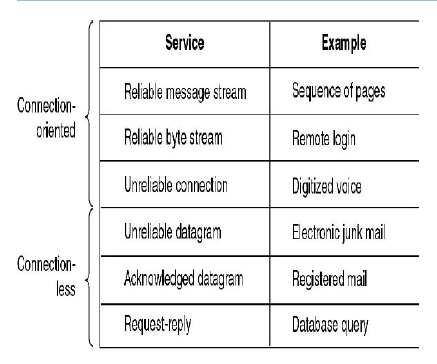
The following table shows an example of 6 different
services
COMPUTER NETWORKS-I × COMPUTER NETWORKS-I Chapter I
Determine path or route
that packets will follow
Use routing protocol based
on a routing algorithm
“Good” path should be least cost
path
Cost : depends on the following
factors.
Average queuing delay
Propagation delay
Bandwidth, mean queue length,
etc.
End systems and routers maintain
routing tables
Dynamic or
static
COMPUTER NETWORKS-I × COMPUTER NETWORKS-I Chapter I
Flow Control
Done by receiving entity
Function to limit amount or rate
of data sent by a transmitting entity
Simplest form: stop-and-wait
procedure
More efficient protocols: Credit
systems Sliding window
Needed at application as well as
network layers
Multiplexing
-Supporting multiple connections
on one machine
-Mapping of multiple connections
at one level to a single connection at another
-Carrying a number of connections
on one fiber optic cable
-Aggregating or bonding ISDN lines to gain bandwidth
COMPUTER NETWORKS-I × COMPUTER NETWORKS-I Chapter I
Guard against loss or damage of
data and control information
Error control is implemented as two separate
functions:
Error detection
Sender inserts error detecting
bits
Receiver checks these bits
If OK, acknowledge
If error, discard packet
Retransmission
If no acknowledge in given time,
re-transmit
Performed at various layers of protocol
COMPUTER NETWORKS-I × COMPUTER NETWORKS-I Chapter I
• Connection oriented data
transfer (virtual circuits)
• Allocates a connection name
during the transfer phase
• the advantages are:
•
Reduced overhead as connection identifiers are shorter than global addresses
•
Routing may be fixed and identified by connection name
•
Entities may want multiple connections – multiplexing
• State information
COMPUTER NETWORKS-I × COMPUTER NETWORKS-I Chapter I
• Global nonambiguity
Global
address identifies unique system
There
is only one system with address X
• Global applicability
It
is possible at any system (any address) to identify any
other
system (address) by the global address of the other
system
Address X identifies that system from anywhere on
the
network
• e.g. MAC address on IEEE 802 networks
COMPUTER NETWORKS-I × COMPUTER NETWORKS-I Chapter I
• Addressing
• Error Control
• Flow Control
• Multiplexing
• Routing
Addressing Level
Level in architecture at which
entity is named
• Unique address for each end
system (computer) and each intermediate system (router)
• Network level address
IP
or internet address (TCP/IP)
Network
service access point or NSAP (OSI)
• Process within the system
Port
number (TCP/IP)
Service access point or
SAP
COMPUTER NETWORKS-I × COMPUTER NETWORKS-I Chapter I
• Business applications
• Resource sharing: end systems
(hosts):
• run application programs
• e.g. Web, email
• at “edge of network”
• client/server model
• client host requests, receives
service from always-on server
• e.g. Web browser/server; email
client/server
• Client/server model is
applicable in an intranet.
E-mail: Now all the companies
uses email as the means of communication
E-commerce: Now teleshopping and
marketing is very popular and finding the
application in business
Mobile users are connected using
network such as laptops palmtops etc
Like wise even home users have increased now and
becoming popular.
Notes
• A Protocol can be defined as a
set of rules governing the exchange of data
between two entities.
• Used for communications between
entities in a system
• Two entities have to speak the
same language to successfully communicate
• Networks are complex and
consist of many “pieces”:
• hosts
• routers
• switches
• links of various media
• applications
• protocols
• reliability
• connection type
How to simplify the complex
structures. A layered structured can be used to reduce the complexity. Most of
the network are organized as a stack of layers or levels each one built over
the other. The number of layers and the name of the layers and the function of each
layer differ from network to network. The purpose of each layer is to offer
service to layer above it. Layer n on one machine carries conversation with
layer n on another machine. The rules and conventions used collectively known
as the layer n protocol. For example consider a five layered network.

The entities comprising the
corresponding layers on different machines are called peers. The peers may be
processes or hardware devices or human beings. Peers communicate using
protocol. No data is sent from layer n to layer n instead they send to the
layer below until the last layer is reached. Between the layers it is the
virtual communication. Between each pair of layers is the interface. It defines
the primitive operation and services what the lower layer makes available to
the upper one. Network designers decide about the function and the number of
layers. It is very important to define a clear interfaces. A set of protocol
and layers is called the network architecture. A list of protocol used by a
certain system one protocol per layer is called a protocol stack.

Consider the above figure
This shows how communication
happens between two systems. A message M is
produced by the layer 5. It is
given to layer 4 and it puts the header in front of the
message and passes to layer 3.
The header includes the control information such as
sequence numbers to allow the
layer 4 on the destination machine to deliver messages in the right order. The
layer 3 breaks up the message into smaller units called packets adding layer 3
header to each packet. In this example M is split into 2 packets M1 and M2.
Layer 3 decides which of the outgoing line to use and sends on that line to
layer 2. Layer 2 adds a header and also a trailer and give the resulting unit
to layer 1 for physical transmission. At the receiving machine the message move
upwards from layer to layer, with header being stripped off as it progresses.
COMPUTER NETWORKS-I × COMPUTER NETWORKS-I Chapter I
• internetwork – interconnection
of networks – also called an “internet”
• Subnetwork – a constituent of
an internet
• Intermediate system – a device
used to connect two networks allowing hosts of the networks to correspond with
each other
Bridge
Routers
• Internet is an example of an
internetwork.
• network of networks”
• “collection of networks
interconnected by routers”
• “a communication medium used by
millions”Email, chat, Web “surfing”, streaming media
• millions of connected computing
devices: hosts, end-systems
– PCs workstations, servers
– PDAs phones, toasters running network
apps
• communication links
– fiber, copper, radio, satellite
– Links have different bandwidth
• routers: forward packets
• Packet: a piece of message
COMPUTER NETWORKS-I × COMPUTER NETWORKS-I Chapter I
No dedicated link present between
the sender and receiver. When a data frame or packet is sent it is sent to the
subnet and to the intermediate system and reaches the destination. The same
message is broken into small packets and sent on the subnet all packets need not
take the same route. The switching elements decide the route.
COMPUTER NETWORKS-I × COMPUTER NETWORKS-I Chapter I
The sender and the receiver has a
dedicated link between them. For example consider the telephone network when a
sender places a call a dedicated link is established between the sender and
receiver as long as the call exists. Then the link is terminated when the call ends.
COMPUTER NETWORKS-I × COMPUTER NETWORKS-I Chapter I

• Spans a large geographic area,
e.g., a country or a continent
• A WAN consists of several
transmission lines and routers Internet is an example of a WAN
• All the machines are connected
using the subnets.
• Compared to LAN the speed is
very less
• Used to connect different LANs
COMPUTER NETWORKS-I × COMPUTER NETWORKS-I Chapter I
It is larger than the LAN and
occupies a city or a group of nearby corporate offices. It uses the same
technology as LAN. The example is the cable TV network. It uses the coaxial
cable. The service provider connects the home TVs this forms a large network. The
service is provided by the cable TV operator. Fiber optic cable is also used.
It can support both voice and data transmission.


