 RSS
RSS Twitter
 Facebook
Showing posts with label Transistor modeling. Show all posts
ANALOG ELECTRONIC CIRCUITS × Transistor modeling

Small signal analysis – fixed bias
• From the above re model,
Zi = [RB || βre] ohms
If RB > 10 βre, then,
[RB || βre] ~= βre
Then, Zi ~=re
• Zo is the output impedance when Vi =0. When Vi =0, ib =0, resulting in open circuit
equivalence for the current source.

• Zo = [RC|| ro ] ohms
• AV
– Vo = - βIb( RC || ro)
• From the re model, Ib = Vi / β re
• thus,
– Vo = - β (Vi / β re) ( RC || ro)
– AV = Vo / Vi = - ( RC || ro) / re
• If ro >10RC,
– AV = - ( RC / re)
• The negative sign in the gain expression indicates that there exists 180o phase
shift between the input and output.
Common Emitter - Voltage-Divider Configuration


• The re model is very similar to the fixed bias circuit except for RB is R1÷÷ R2 in the
case of voltage divider bias.
• Expression for AV remains the same.
Zi = R1 ÷÷ R2 ÷÷ b re
Zo = RC
• From the re model, Ib = Vi / b re
• thus,
Vo = - b (Vi / b re) ( RC || ro)
• AV = Vo / Vi = - ( RC || ro) / re
o If ro >10RC,
AV = - ( RC / re)
Common Emitter - Unbypassed Emitter-Bias Configuration


• Applying KVL to the input side:
Vi = Ib bre + IeRE
Vi = Ib bre +(b +1) IbRE
Input impedance looking into the network to the right of RB is
Zb = Vi / Ib = bre+ (b +1)RE
Since b>>1, (b +1) = b
Thus,
Zb = Vi / Ib = b (re+RE)
• Since RE is often much greater than re,
Zb = bRE,
•
Zi = RB||Zb
• Zo is determined by setting Vi to zero, Ib = 0 and b Ib can be replaced by open
circuit equivalent. The result is,
• Zo = RC
• AV : We know that, Vo = - IoRC
= - bIbRC
= - b(Vi/Zb)RC
AV = Vo / Vi = - b(RC/Zb)
Substituting, Zb = b(re + RE)
AV = Vo / Vi = - b[RC /(re + RE)]
RE >>re, AV = Vo / Vi = - b[RC /RE]
• Phase relation: The negative sign in the gain equation reveals a 180o phase shift
between input and output.
Emitter – follower


• Zi = RB || Zb
• Zb = bre+ (b +1)RE
• Zb = b(re+ RE)
• Since RE is often much greater than re, Zb = bRE
• To find Zo, it is required to find output equivalent circuit of the emitter follower
at its input terminal.
• This can be done by writing the equation for the current Ib.
Ib = Vi / Zb
Ie = (b +1)Ib
= (b +1) (Vi / Zb)
• We know that, Zb = bre+ (b +1)RE substituting this in the equation for Ie we get,
Ie = (b +1) (Vi / Zb)
= (b +1) (Vi / bre+ (b +1)RE )
Ie = Vi / [bre/ (b +1)] + RE
• Since (b +1) = b,
Ie = Vi / [re+ RE]
• Using the equation Ie = Vi / [re+ RE] , we can write the output equivalent circuit as,

• As per the equivalent circuit,
Zo = RE||re
• Since RE is typically much greater than re, Zo @ re
• AV – Voltage gain:
• Using voltage divider rule for the equivalent circuit,
Vo = Vi RE / (RE+ re)
AV = Vo / Vi = [RE / (RE+ re)]
• Since (RE+ re) @ RE,
AV @ [RE / (RE] @ 1
•
• Phase relationship
As seen in the gain equation, output and input are in phase.
Common base configuration
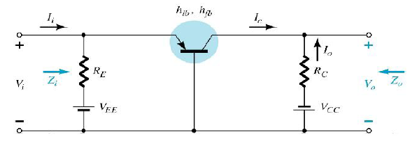
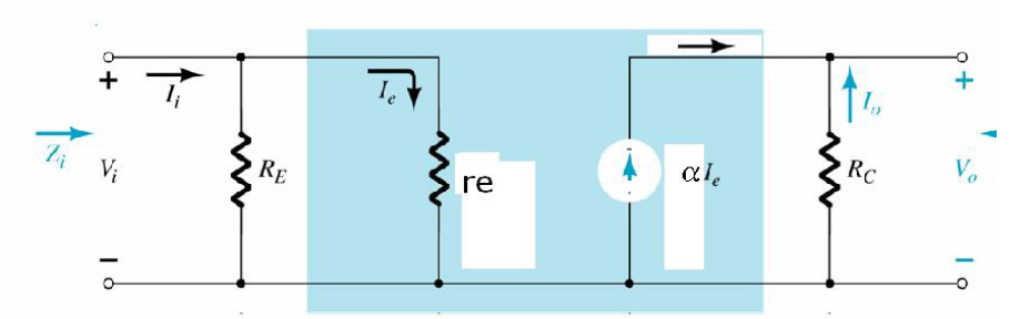
Small signal analysis
• Input Impedance: Zi = RE||re
• Output Impedance: Zo = RC
• To find, Output voltage,
Vo = - IoRC
Vo = - (-IC)RC = aIeRC
o Ie = Vi / re, substituting this in the above equation,
Vo = a (Vi / re) RC
Vo = a (Vi / re) RC
Voltage Gain: AV:
AV = Vo / Vi = a (RC/ re)
a @ 1; AV = (RC/ re)
Current gain
Ai = Io / Ii
Io = - a Ie = - a Ii
Io / Ii = - a @ -1
Phase relation: Output and input are in phase.
ANALOG ELECTRONIC CIRCUITS × Transistor modeling
• For the hybrid equivalent model, the parameters are defined at an operating point.
• The quantities hie, hre,hfe, and hoe are called hybrid parameters and are the
components of a small – signal equivalent circuit.
• The description of the hybrid equivalent model will begin with the general two
port system.

• The set of equations in which the four variables can be related are:
• Vi = h11Ii + h12Vo
• Io = h21Ii + h22Vo
• The four variables h11, h12, h21 and h22 are called hybrid parameters ( the mixture
of variables in each equation results in a “ hybrid” set of units of measurement for
the h – parameters.
• Set Vo = 0, solving for h11, h11 = Vi / Ii Ohms
• This is the ratio of input voltage to the input current with the output terminals
shorted. It is called Short circuit input impedance parameter.
• If Ii is set equal to zero by opening the input leads, we get expression for h12:
h12 = Vi / Vo , This is called open circuit reverse voltage ratio.
• Again by setting Vo to zero by shorting the output terminals, we get
h21 = Io / Ii known as short circuit forward transfer current ratio.
• Again by setting I1 = 0 by opening the input leads, h22 = Io / Vo . This is known as
open – circuit output admittance. This is represented as resistor ( 1/h22)
• h11 = hi = input resistance
• h12 = hr = reverse transfer voltage ratio
• h21 = hf = forward transfer current ratio
• h22 = ho = Output conductance
Hybrid Input equivalent circuit

Hybrid output equivalent circuit

Complete hybrid equivalent circuit

Common Emitter Configuration - hybrid equivalent circuit

• Essentially, the transistor model is a three terminal two – port system.
• The h – parameters, however, will change with each configuration.
• To distinguish which parameter has been used or which is available, a second
subscript has been added to the h – parameter notation.
• For the common – base configuration, the lowercase letter b is added, and for
common emitter and common collector configurations, the letters e and c are used
respectively.
ANALOG ELECTRONIC CIRCUITS × Transistor modeling
• The key to transistor small-signal analysis is the use of the equivalent circuits
(models). A MODEL IS A COMBINATION OF CIRCUIT ELEMENTS
LIKE VOLTAGE OR CURRENT SOURCES, RESISTORS, CAPACITORS
etc, that best approximates the behavior of a device under specific operating
conditions. Once the model (ac equivalent circuit) is determined, the schematic
symbol for the device can be replaced by the equivalent circuit and the basic
methods of circuit analysis applied to determine the desired quantities of the
network.
• Hybrid equivalent network – employed initially. Drawback – It is defined for a set
of operating conditions that might not match the actual operating conditions.
• re model: desirable, but does not include feedback term
• model: model of choice.p• Hybrid
AC equivalent of a network
• AC equivalent of a network is obtained by:
• Setting all dc sources to zero and replacing them by a short – circuit equivalent
• Replacing all capacitors by short – circuit equivalent
• Removing all elements bypassed by the short – circuit equivalents
• Redrawing the network in a more convenient and logical form.


re model
• In re model, the transistor action has been replaced by a single diode between
emitter and base terminals and a controlled current source between base and
collector terminals.
• This is rather a simple equivalent circuit for a device


