 RSS
RSS Twitter
 Facebook
Showing posts with label Power Amplifiers. Show all posts
ANALOG ELECTRONIC CIRCUITS × Power Amplifiers

Ø The transformer can step up or step down a voltage applied to primary coil .

Transformer coupled class A PA
• A form of class A amplifier having maximum efficiency of 50% uses
transformer to couple the output signal to the load.
Impedance transformation
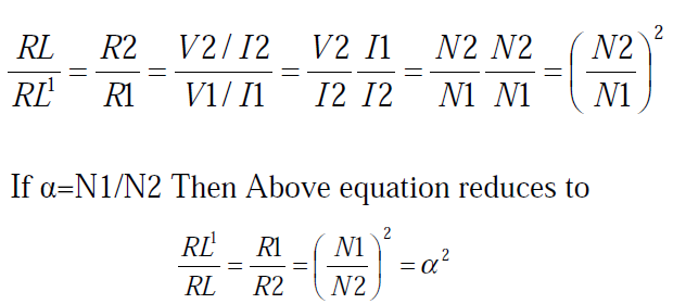
Load resistance reflected to the primary side as,

Transformer coupled amplifier
• Drawing DC and AC load line
• Signal swing and output AC power

Power across the load can be expressed as

• with the output ac power then calculated using
PL=IL
2(rms) RL
ANALOG ELECTRONIC CIRCUITS × Power Amplifiers
It is a fixed bias circuit

DC bias operation
The DC bias set by Vcc and Rb
Collector current IC=βIB
Collector –emitter voltage
VCE=VCC-ICRC
Load line

Power considerations
Ø The power into an amplifier is provided by the power supply
Ø With no input supply, current drawn is collector bias current ICq.
pi(dc)=VCCICq
Output power
Ø The output voltage and current varying around the bias point provide ac
power to the load.
Using rms signals
Ø P0(ac)=VCE(rms)IC(rms)
=I2
C(rms) Rc
=V2
C(rms)/Rc
Ø Using peak signals
The ac power delivered to the load is
p0={VCE(p) IC(p)} / 2
or = {I2
c(p)/2} Rc
={V2
CE(p)}/2Rc
Ø Using peak-peak signals
P0(ac)={VCE(p-p) IC(p-p)}/8
= {I2
c(p-p)/8} Rc
={V2
CE(p)}/8Rc
Efficiency
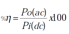
Ø Efficiency of an amplifier represents the amount of ac power delivered from
dc source. It can be calculated using
Maximum Efficiency
Ø Maximum voltage swing VCE(p-p)=VCC
Ø Maximum current swing IC(p-p)=VCC/RC
Ø Maximum power

Ø The maximum power input evaluated using dc bias current set to half of the
maximum value….
Ø Maximum Pi(dc)=VCC(maximum IC)

maximum Pi(dc)} x100

= 25%
Maximum efficiency
Ø The maximum efficiency of a class A series fed amplifier is thus seen to be
25%.
Ø The maximum efficiency occurs only for ideal conditions of both voltage
and current swing .thus practical circuits will have less than this percentage.
ANALOG ELECTRONIC CIRCUITS × Power Amplifiers
• Class D amplifiers are much more efficient than Class AB power amplifiers.
As such, Class D amplifiers do not need large transformers and heavy
heatsinks, which means that they are smaller and lighter in weight than an
equivalent Class AB amplifier. All power devices in a Class D amplifier are
operated in on/off mode.
• These amplifiers use pulse width modulation,
ANALOG ELECTRONIC CIRCUITS × Power Amplifiers
• Class C amplifiers conduct less than 50% of the input signal and the
distortion at the output is high, but high efficiencies (up to 90%) are
possible. Some applications (for example, megaphones) can tolerate the
distortion. A much more common application for Class C amplifiers is in RF
transmitters, where the distortion can be vastly reduced by using tuned loads
on the amplifier stage.
• The input signal is used to roughly switch the amplifying device on and off,
which causes pulses of current to flow through a tuned circuit.

ANALOG ELECTRONIC CIRCUITS × Power Amplifiers
• A practical circuit using Class B elements is the complementary pair or
"push–pull" arrangement. Here, complementary or quasi-complementary
devices are used to each amplify the opposite halves of the input signal,
which is then recombined at the output. This arrangement gives excellent
efficiency, but can suffer from the drawback that there is a small mismatch
at the "joins" between the two halves of the signal..
• Class AB sacrifices some efficiency over class B in favor of linearity, so will
always be less efficient (below 78.5%). It is typically much more efficient
than class A.

ANALOG ELECTRONIC CIRCUITS × Power Amplifiers
• Class B amplifiers only amplify half of the input wave cycle. As such they
create a large amount of distortion, but their efficiency is greatly improved
and is much better than Class A. Class B has a maximum theoretical
efficiency of 78.5% (i.e., π/4). This is because the amplifying element is
switched off altogether half of the time, and so cannot dissipate power.
• A single Class B element is rarely found in practice, though it can be used in
RF power amplifier where the distortion levels are less important. However
Class C is more commonly used for this.

ANALOG ELECTRONIC CIRCUITS × Power Amplifiers
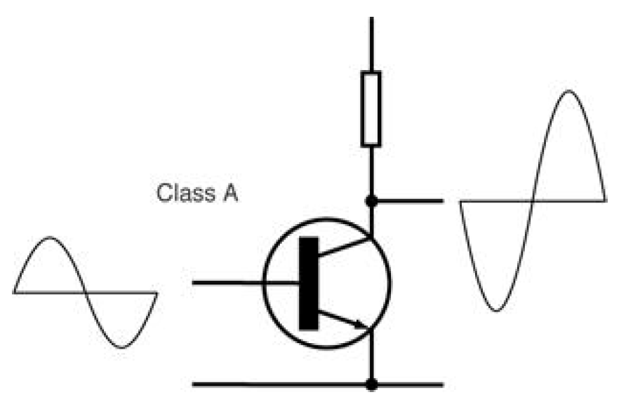
• Class A amplifying devices operate over the whole of the input cycle such
that the output signal is an exact scaled-up replica of the input with no
clipping. Class A amplifiers are the usual means of implementing smallsignal
amplifiers. They are not very efficient. a theoretical maximum of 50%
is obtainable with inductive output coupling and only 25% with capacitive
coupling.
• In a Class A circuit, the amplifying element is biased so the device is always
conducting to some extent, and is operated over the most linear portion of its
characteristic curve Because the device is always conducting, even if there is
no input at all, power is drawn from the power supply. This is the chief
reason for its inefficiency.
ANALOG ELECTRONIC CIRCUITS × Power Amplifiers
Ø Amplifier classes represent the amount the output signal varies over one
cycle of operation for a full cycle of input signal
Ø So the following classes of PA are defined
Ø Class A
Ø Class B
Ø Class AB
Ø Class C
Ø Class D


