 RSS
RSS Twitter
 Facebook
Showing posts with label Oscillator. Show all posts
ANALOG ELECTRONIC CIRCUITS × Oscillator
• A Crystal Oscillator is basically a tuned circuit Oscillator using a piezoelectric
crystal as a resonant circuit.
• The crystal ( usually quartz) has a greater stability in holding constant at
whatever frequency the crystal is originally cut to operate.
• Crystal Oscillators are used whenever great stability is required, such as
communication transmitters and receivers.
Characteristics of a Quartz Crystal
• A quartz crystal exhibits the property that when mechanical stress is applied
across one set of its faces, a difference of potential develops across the opposite
faces.
• This property of a Crystal is called ‘ Piezoelectric effect’.
• Similarly, a voltage applied across one set of faces of the Crystal causes
mechanical distortion in the Crystal shape.
• When alternating voltage is applied to a crystal, mechanical vibrations are set up
– these vibrations having a natural resonant frequency dependent on the Crystal.
• Although the Crystal has electromechanical resonance, we can represent the
Crystal action by equivalent electrical circuit as shown.

The inductor L and the capacitor C represent electrical equivalents of Crystal mass
and compliance respectively, whereas resistance R is an electrical equivalent of the
crystal structures internal friction. The shunt capacitance CM represents the
capacitance due to mechanical mounting of the crystal. Because the crystal losses,
represented by R, are small, the equivalent crystal Q factor is high – typically 20,000.
Values of Q up to almost 106 can be achieved by using Crystals. The Crystal can
have two resonant frequencies. One resonant condition occurs when the reactances of
the series RLC leg are equal. For this condition, the series – resonant impedance is
very low ( equal to R). The other resonant condition occurs at a higher frequency
when the reactance of the series resonant leg equals the reactance of the capacitor CM.
This is parallel resonance or antiresonance condition of the Crystal,
At this frequency, the crystal offers very high impedance to the external circuit.
To use the crystal properly, it must be connected in a circuit so that its low
impedance in the series resonant operating mode or high impedance in the
antiresonant operating mode is selected.
ANALOG ELECTRONIC CIRCUITS × Oscillator

The Hartley oscillator is similar to the Colpitts. The tank circuit has two inductors and
one capacitor. The calculation of the resonant frequency is the same.
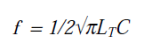
LT= L1 + L2 + 2M
where, M is mutual coupling

ANALOG ELECTRONIC CIRCUITS × Oscillator

• The Colpitts oscillator utilizes a tank circuit (LC) in the feedback loop. The
resonant frequency can be determined by the formula below. Since the input
impedance affects the Q, an FET is a better choice for the active device.

• An Op amp Colpitts Oscillator circuit can also be used wherein the Op amp
provides the basic amplification needed and the Oscillator frequency is set by an
LC feedback network.
ANALOG ELECTRONIC CIRCUITS × Oscillator

• If a transistor is used as the active element of the amplifier stage, the output of the
feedback network is loaded appreciably by the relatively low input resistance
( hie) of the transistor.
• An emitter – follower input stage followed by a common emitter amplifier stage
could be used.If a single transistor stage is desired, the use of voltage – shunt
feedback is more suitable. Here, the feedback signal is coupled through the
feedback resistor R’ in series with the amplifier stage input resistance ( Ri).
f = (1/2pRC)[1/Ö 6 + 4(RC / R)]
hfe > 23 + 29 (R/RC) + 4 (RC / R)
ANALOG ELECTRONIC CIRCUITS × Oscillator

• The amplifier stage is self biased with a capacitor bypassed source resistor Rs and
a drain bias resistor RD . The FET device parameters of interest are gm and rd.
• |A| = gmRL, where RL = (RDrd / RD + rd)
• At the operating frequency, we can assume that the input impedance of the
amplifier is infinite.
• This is a valid approximation provided, the oscillator operating frequency is low
enough so that FET capacitive impedances can be neglected.
• The output impedance of the amplifier stage given by RL should also be small
compared to the impedance seen looking into the feedback network so that no
attenuation due to loading occurs.
ANALOG ELECTRONIC CIRCUITS × Oscillator

• The phase shift oscillator utilizes three RC circuits to provide 180º phase shift that
when coupled with the 180º of the op-amp itself provides the necessary feedback
to sustain oscillations.
• The gain must be at least 29 to maintain the oscillations. The frequency of
resonance for the this type is similar to any RC circuit oscillator:
fr = 1/26RC
ANALOG ELECTRONIC CIRCUITS × Oscillator
• An amplifier with positive feedback results in oscillations if the following
conditions are satisfied:
– The loop gain ( product of the gain of the amplifier and the gain of the
feedback network) is unity
– The total phase shift in the loop is 0°
• If the output signal is sinusoidal, such a circuit is referred to as sinusoidal
oscillator.

When the switch at the amplifier input is open, there are no oscillations. Imagine that a
voltage Vi is fed to the circuit and the switch is closed. This results in Vo = AV Vi and
bVo = Vf is fed back to the circuit. If we make Vf = Vi, then even if we remove the input
voltage to the circuit, the output continues to exist.
Vo = AV Vi
bVo = Vf
b AV Vi = Vf
If Vf has to be same as Vi, then from the above equation, it is clear that, b AV =1.
Thus in the above block diagram, by closing the switch and removing the input, we are
able to get the oscillations at the output if b AV =1, where b AV is called the Loop gain.
Positive feedback refers to the fact that the fed back signal is in phase with the input
signal. This means that the signal experiences 0° phase shift while traveling in the loop.
The above condition along with the unity loop gain needs to be satisfied to get the
sustained oscillations. These conditions are referred to as ‘Barkhausen criterion’.
Another way of seeing how the feedback circuit provides operation as an oscillator is
obtained by noting the denominator in the basic equation
Af = A / (1+bA).
When bA = -1 or magnitude 1 at a phase angle of 180°, the denominator becomes 0 and
the gain with feedback Af becomes infinite.Thus, an infinitesimal signal ( noise voltage)
can provide a measurable output voltage, and the circuit acts as an oscillator even without
an input signal.


