 RSS
RSS Twitter
 Facebook
Showing posts with label Local Area Networks. Show all posts
COMPUTER NETWORKS-I × Local Area Networks
• Traveling Users
– 20% to 40% of work force moves
every year
• net admin’s biggest headache
• largest expense in managing
networks. Moves may require...
– recabling
– readdressing and
reconfiguration
– VLANs provide a way to control
these costs. As long as the user still
belongs to the same VLAN...
• simply configure the new switch
port to that VLAN
• router configuration remains
intact
– Routers provide an effective
firewall against broadcasts
– Adding VLANs can extend a
router’s firewall capabilities to the “switch
fabric”
– The smaller the VLAN, the
smaller the number of users that are effected
by broadcasts
– Shared LANs are easy to
penetrate...simply plug into the shared hub.
– VLANs increase security by ...
• restricting number of users in
a VLAN
• preventing user access without
authorization
• configuring all unused ports to
the “Disabled” setting
• control access by
– addresses
– application types
– protocol types
• Hub Replacement &
Segmentation
– The ports on a non-intelligent
hub can only be assigned one VLAN.
– Replacing hubs with switches is
relatively cheap compared to the benefit
gained.
– In the graphic, replacing the
core hub in an extended star topology with a
VLAN capable switch effectively
microsegments one shared LAN into six.
COMPUTER NETWORKS-I × Local Area Networks
• In a typical shared LAN...
– Users are grouped physically
based on the hub they are plugged into
– Routers segment the LAN and
provide broadcast firewalls
• In VLANs...
– you can group users logically
by function, department or application in use
– configuration is done through
proprietary software
– VLANs can logically segment
users into different subnets (broadcast
domains)
– Broadcast frames are only
switched between ports on the switch or
switches with the same VLAN ID.
– Users can be logically group
via software based on:
• port number
• MAC address
• protocol being used
• application being used

The above figure shows the
difference between a LAN and a VLAN
• VLANs...
– work at Layer 2 & 3
– control network broadcasts
– allow users to be assigned by
net admin.
– provide tighter network
security
The figure shows the formation of a VLAN

• A router provides connection
between different VLANs
• For example, you have VLAN1 and
VLAN2.
– Within the switch, users on
separate VLANs cannot talk to each other
(benefit of a VLAN!)
– However, users on VLAN1 can
email users on VLAN2 but they need a
router to do it.
• Switches make filtering and
forwarding decisions based on data in the frame.
• There are two techniques used.
– Frame Filtering--examines
particular information about each frame (MAC
address or layer 3 protocol type)
– Frame Tagging--places a unique
identifier in the header of each frame as it
is forwarded throughout the network backbone.
• Three methods for implementing
VLANs
– Port-Centric
– Static
– Dynamic
• Each switched port can be
assigned to a VLAN. This...
– ensures ports that do not share
the same VLAN do not share broadcasts.
– ensures ports that do share the same VLAN will
share broadcasts.
COMPUTER NETWORKS-I × Local Area Networks
· Interconnect
LANs of different types
· Example ethernet
and token ring
· These differ in
frame format, opeartion and speed and these issues to be taken
care of
· Since the frame
formats are different reformatting is done and new FCS is used.
But adds processing overhead.
· Since the data
rate is different the bridge should have sufficient buffering capacity
· Two approaches
used are : translational bridging
source route transparent bridging
Switch

• used to concentrate connectivity
• combine the connectivity of a
hub with the traffic regulation of a bridge
• switch frames from incoming
ports to outgoing ports providing each port with full
bandwidth
• provide separate data paths
switch functions
– Address learning
– Forward/filter decision
– Loop avoidance
COMPUTER NETWORKS-I × Local Area Networks
· First the src
stn. Transmits the single route broadcast frame on its LAN without the route
designator field.
· this frame should
appear exactly once and hence selected bridges form spanning tree
· Once the
selected bridge at the first hop receives this frame
§ inserts an
incoming LAN number
§ bridge number
§ outgoing LAN
number in the routing information field
· Then forwards on
outgoing LAN
· At the other hop
when a selected bridge receives this frame inserts bridge number and outgoing
LAN number and forwards on outgoing LAN
· Non selected
bridge simply ignore this frame
· Once the
receiver gets this frame it broadcasts all routes broadcast frame with no route
designator fields
· This frame
generates all possible routes back to the src stn
· After collecting
all routes the source station selects the best route and saves it
· To prevent all
routes broad cast frames from circulating in the network, the bridge first
checks whether the outgoing LAN number is already recorded, if so it does not
forward the frame
COMPUTER NETWORKS-I × Local Area Networks
• CSMA/CD community preferred to
use transparent bridges due to their simplicity.
• The Token Ring community,
however, preferred source routing bridges.
• In source routing, the sending
station knows whether the destination is on the same network. If it is not, the
sender sets the higher destination address bit to 1 and includes the exact path
to the frame header.
• The path is a sequence of
alternating bridge and LAN addresses (4bits/12bits).
• This requires that each machine
know the topology and can construct a path to any receiver.
• Instead, the sender first
broadcasts a discovery frame asking the receiver to signal himself. In
the return trip bridges record their addresses in the frame header and the path
is formed.
• Problem: Too many frame loose in the network.
COMPUTER NETWORKS-I × Local Area Networks
• Bridges exchange bridge
protocol data units (BPDUs). These have configuration messages consisting of:
– Root ID, bridge assumed by
sending bridge to be the root
– Transmitting bridge ID
– Cost of least cost path to the
root of which the transmitting bridge is aware
• When a bridge receives a
configuration message from a neighbor bridge, it compares this with what it
would transmit over that port. Note that it will add the cost to the received
message before comparison. It saves the best configuration
message received for each port.
If the saved configuration is better than what it would transmit it stops
transmitting BPDUs over that
• All bridges start by
transmitting on all ports:
– Root id is own id
– Transmitting id is own id
– Cost is 0
– (Port id of port)
– Which is a better message?
First compare root ID, lower is
better
If tie, next compare costs, lower
is better
If tie, next compare transmitting
ID, lower is better
If still tie, port id is tie breaker
Eventually only the root bridge is transmitting.
COMPUTER NETWORKS-I × Local Area Networks
• for increased reliability,
desirable to have redundant, alternate paths from source to dest
• with multiple simultaneous
paths, cycles result - bridges may multiply and forward frame forever
• solution: organize bridges in a spanning tree by
disabling subset of interfaces

• As the system grows a complex
graph of many networks and many bridges
appear.
• Frames may loop through
networks!
• Bridges communicate to build
dynamic spanning tree graph, showing the
topology of the network.
• Spanning tree graphs avoid
loops.
• First the bridge with the
smallest serial number becomes the root of the tree.
• Next the tree is constructed.
LAN’s are placed on the nodes, and bridges are
placed on the vertices.
• If a LAN or bridge is no longer
present the tree is updated.
• All networks are on the tree
but to prevent loops some of the bridges are left off
the graph. This makes the graph a
tree
• Elect a single bridge among all
bridges as the root bridge. The algorithm will
select the root bridge as the one
with the lowest bridge id.
• Each bridge (except root)
determines the least cost path (shortest path with respect
to some metric, say hops) from
itself to the root bridge through each of its ports.
The port with least cost is the
root port for that bridge. In case of ties use the
smallest port id.
• Elect a designated bridge for
each LAN from the bridges directly connecting to
that LAN. The designated bride is the one closest to
the root bridge. In case of
ties it is the one with the
lowest bridge id. The port that connects the designated
bridge and the LAN is the
designated port for that LAN.
• Ports in the spanning tree are
all root ports and designated ports. Other ports are
in the blocking state.
• Data traffic is forwarded to
and received from ports in the spanning tree only.
Example
Sample topology

using spanning tree

COMPUTER NETWORKS-I × Local Area Networks
• Main idea: A bridge should
easily connect any set of LAN’s together and make
the connection transparent to the
stations.
• No maintenance, software
upgrade and routing table upload should be necessary.
• The bridge listens to both
network at all times.
• Any frame received is buffered.
• Next the bridge should be able
to decide if the frame was addressed to a station in
the same network. If not, it
should select the proper LAN and broadcast the frame
there.
• Backward Learning:
• The bridge keeps a table
containing hashed (address, network) entry pairs.
• The bridge accepts any frame,
if the destination address is in the table then the frame is forwarded to the
proper network, otherwise the frame is broadcast onto all networks
(except the one its coming from).
• For each incoming frame the bridge
also read the source address and updates the hash table by
inserting the source address and the network id into the tables.
• Entries in the table can live
for a certain time, and if there is no packet
traffic from or to that an
address the entry is removed from the table.
• Maintain a forwarding database
or cache of station MAC addresses and the bridge port that the stations are on
• Promiscuously listen to packets
arriving on any port
• For each packet arriving at the
bridge:
• Store the stations source
address and arriving port in the cache (if an entry
already exists for an address
update if different)
– determine if the destination
address is in the cache
• If entry then forward only on
the appropriate port unless the port is the same as the arrival port
• If no such entry then forward
packet on all segments except the one the packet was received on.
– Age each entry in the cache and delete after an
appropriate time
COMPUTER NETWORKS-I × Local Area Networks

Interconnection by bridge

• The no frills bridge : simply
transmit all traffic from one LAN segment onto all
the other segments
– Advantages: two stations can be
transmitting at the same time. Bridge
will buffer a packet until it can
transmit on a LAN
– Disadvantages: total bandwidth
still that can be safely utilized is still the
minimum bandwidth of each LAN segment
• Keeping a database of all
stations on each LAN segment
– Manually enter addresses in
such a database
– Partition addresses into ranges
on each LAN
• Eg. LAN 1 has 1-50, LAN 2 has
51-100, LAN 3 has 101-150
– Have the MAC address be
hierarchically divided into a LAN address and a
station address (like the IP
address)
– None of these solutions are
really used
• Better solution: the
transparent learning bridge
– Learn on which segment a
station resides
– Transmit a packet only onto the
correct segment
• bridges learn which
hosts can be reached through which interfaces: maintain
filtering tables
– when frame received, bridge “learns”
location of sender: incoming LAN
segment
– records sender location in
filtering table
• filtering table entry:
– (Node LAN Address, Bridge
Interface, Time Stamp)
– stale entries in Filtering
Table dropped (TTL can be 60 minutes)
• filtering procedure:
– if destination is on LAN
on which frame was received
• then drop the frame
• else { lookup filtering
table
• if entry found for
destination
• then forward the frame
on interface indicated;
• else flood; /*
forward on all but the interface on
which the frame
arrived*/
• }
COMPUTER NETWORKS-I × Local Area Networks
Limitations of
hubs
• single collision domain results
in no increase in max throughput
– multi-tier throughput same as
single segment throughput
• individual LAN restrictions
pose limits on number of nodes in same collision
domain and on total allowed
geographical coverage
• cannot connect different
Ethernet types (e.g., 10BaseT and 100baseT)
Bridges
• A network component connecting
LAN’s together.
• Operates only in the data link
layer, thus is can handle any network protocol used.
• May be used
– to divide the large expensive
and hard to manage network into smaller
LAN’s.
– split networks that became
loaded over time.
– to handle larger distances.
– to block some traffic leaking
outside the network.
Link Layer devices: operate on
Ethernet frames, examining frame header and selectively
forwarding frame based on its
destination
Bridge isolates collision domains
since it buffers frames
When frame is to be forwarded on
segment, bridge uses CSMA/CD to access segment
and transmit
• Bridge advantages:
– Isolates collision domains
resulting in higher total max throughput, and
does not limit the number of
nodes nor geographical coverage
– Can connect different type
Ethernet since it is a store and forward device
– Transparent: no need for any
change to hosts LAN adapters
• bridges filter packets
– same-LAN -segment frames not forwarded
onto other LAN segments
• forwarding:
– how to know which LAN segment
on which to forward frame?
– looks like a routing problem
(more shortly!)
• Reasons for bridges
– Limited number of stations on a
LAN segment or ring
– Limited distance for executing
CSMA / CD algorithm or distance one
wants a token traveling on a ring
– Limited traffic on a single
LAN: available bandwidth must be shared by
all stations
• Interconnecting networks
– Networks connected at the
physical layer are connected by a repeater
– Networks connected at the MAC
or link layer are connected by bridges
– Networks connected at the
network layer are connected by routers
– Higher layer interconnection
devices that perhaps execute additional
functions such as protocol
conversion are often called gateways
• Bridges
– Devices for gluing together
LANs so that packets can be forwarded from
one LAN to the other
COMPUTER NETWORKS-I × Local Area Networks
• Ad hoc network: IEEE 802.11
stations can dynamically form network without AP
• Applications:
– “laptop” meeting in conference
room, car
– interconnection of “personal”
devices
– battlefield

Frame structure

There are three types of frames
Management frame-used for station
association and dissociation with the AP
timing and synchronization and
authentication and deauthentication
Control frame-used for
handshaking and for positive ack
Data frame-for transmission of
data
MAC header provides information
on frame control, duration, addressing and
sequence control
MAC sublayer is responsible for
channel access procedures, pdu addressing
,formatting, fragmentation and
reassembly of MSDUs
supports security services
through authentication and privacy mechanisms
management services support
roaming within and ESS and assist stations in
power management.
The figure on the
next figure shows the MAC architecture

It is defined using the
coordination functions
DCF offers the contention service
where the stations have to contend to use the channel.
Uses CSMA/CA
The basic operation is
as follows
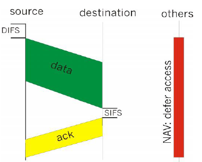
• 802.11 CSMA: sender
• - if sense channel idle for DISF
sec.
• then transmit entire frame (no
collision detection)
• -if sense channel busy then
binary backoff
• 802.11 CSMA receiver:
• if received OK
• return ACK after SIFS

– receiver: reply with short CTS:
clear to send
• CTS reserves channel for
sender, notifying (possibly hidden) stations
• avoid hidden station collisions
• RTS and CTS short:
– collisions less likely, of
shorter duration
– end result similar to collision
detection
• IEEE 802.11 alows:
– CSMA
– CSMA/CA: reservations
– polling from AP
COMPUTER NETWORKS-I × Local Area Networks
• Basic Service Set (BSS)
contains:
– wireless hosts
– access point (AP): base station
• BSS’s combined to form
distribution system (DS) to form a extended service set
ESS
• ESS provide gateway access for
wireless users into wired network. This access is
done through a device called portal

The figure shows the distributed system.
COMPUTER NETWORKS-I × Local Area Networks

Wireless LAN 802.11
· Protocol stack
· Frame structure
· MAC protocol
· services
The above figure shows the
protocol stack of the wireless LAN
Why not Ethernet ?
Several reasons as to why it
cannot be used
• difficult to detect collisions
• not controlled as the wired
ones
• Hidden station problem
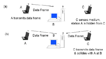
The above figure shows the hidden station problem
COMPUTER NETWORKS-I × Local Area Networks
• As for 802.5 except:
• Station seizes token by
aborting token transmission
• Once token captured, one or
more data frames transmitted
• New token released as soon as
transmission finished (early token release in 802.5)
• Handle two type of traffic
• synchronous-tight transfer
delay requirement-voice or video
• asynchronous-greater delay
tolerance-data
• TTRT-target token rotation
time-all stations agree to operate
• Every station is allotted time
S during which it can send the synchronous traffic.
• If the sum of Si times is
smaller than TTRT then token will return to every node
in less than 2 TTRT sec.
• and hence meets the delay
requirement
• Each station maintains
TRT-token rotation timer: measures the time elapsed since
the station last received the
token.
• When a station receives the
token it calculates THT-token hold time:
THT=TTRT=TRT
• if THT>0 all synchronous and
asynchronous traffic is sent
• if THT<0 only synchronous traffic is allowed
COMPUTER NETWORKS-I × Local Area Networks
• Let there be M stations
• b bits delay in stations
• The delay in interface is Mb
bits
• typically b=2.5
• d total ring length
• additional delay is d/v or dR/v
v-delay in medium
• v=2*108 m/sec
• therefore it is 5microsec to
travel 1 kms
• ring latency is defined as the
time that it takes for a bit to travel around ring is
given by
• T’=d/v+Mb/R and T’R= dR/v+Mb
bits
• Example
• Let R=4Mbps M=20 stations
separated by 100m b=2.5
• Latency= 20*100*4*106 /2*108 +20*2.5=90 bits

• IEEE 802.5-After the last bit
arrives the token is inserted
• IBM token ring-after the header
bit arrives the token is inserted
• IEEE 802.5 and IBM token ring
26Mbps- after last bit transmitted the token is inserted
• Conclusion-improves efficiency in case of the
third case.
COMPUTER NETWORKS-I × Local Area Networks

Fiber Distributed Data Interface
(FDDI) came about because system managers became
concerned with network
reliability issues as mission-critical applications were
implemented on high-speed
networks.
FDDI is frequently used as a
backbone technology and to connect high-speed computers in a LAN.
FDDI has four specifications:
MediaAccessControl—
defineshowthemediumis
accessedframe formattoken handlingaddressing algorithm for
calculating a cyclic redundancy
check and error-recovery mechanisms
FDDI has four specifications:
Physical Layer Protocol—defines
data encoding/decoding procedures
clocking requirements framing
FDDI has four specifications:
Physical Layer Medium—defines the
characteristics of the transmission medium fiber
optic link power levels bit error
rates optical components connectors
FDDI has four specifications:
Station Management—defines the
FDDI station configuration ring configuration ring
control features stationinsertion
and removal initialization fault isolation and recovery
Recovery collection of statistics
Unlike CSMA/CD networks, such as
Ethernet, token-passing networks are deterministic-
-you can calculate the maximum
time that will pass before any end station will be able to
transmit. FDDI's dual ring makes
FDDI very reliable.
FDDI supports real-time
allocationof network bandwidth, making it ideal for a variety of
different application types. FDDI
provides this support by defining two types of traffic –
synchronous and asynchronous.
• Synchronous traffic can consume
a portion of the 100 Mbps total bandwidth of an
FDDI network, while asynchronous
traffic can consume the rest.
• Synchronous bandwidth is
allocated to those stations requiring continuous
transmission capability. This is
useful for transmitting voice and video
information.
• The remaining bandwidth is used
for asynchronous transmissions.
• The FDDI SMT specification
defines a distributed bidding scheme to allocate
FDDI bandwidth
• Asynchronous bandwidth is
allocated using an eight-level priority scheme. Each
station is assigned an
asynchronous priority level.
• FDDI also permits extended
dialogues, in which stations may temporarily use all
asynchronous bandwidth.
• The FDDI priority mechanism can
lock out stations that cannot use synchronous
bandwidth and that have too low
an asynchronous priority.
• FDDI uses an encoding scheme
called 4B/5B. Every 4 bits of data are sent as a 5
bit code. The signal sources in
FDDI transceivers are LEDs or lasers.
• FDDI specifies a 100 Mbps,
token-passing, dual-ring LAN that uses a fiber-optic
transmission medium.
• It defines the physical
layer and media access portion of the data link layer,
which is similar to IEEE 802.3
and IEEE 802.5 in its relationship to the OSI
Model.
• Although it operates at faster
speeds, FDDI is similar to Token Ring.
• The two networks share a few
features, such as topology (ring) and media access
technique (token-passing). A characteristic
of FDDI is its use of optical fiber as a
transmission medium.
• Optical fiber is exploding in
popularity as a networking medium, being installed
at a rate of 4000 miles per day in the United
States.
• Single-mode fiber is capable of
higher bandwidth and greater cable run distances
than multi-mode fiber.
• Because of these
characteristics, single-mode fiber is often used for interbuilding
connectivity while multi-mode
fiber is often used for intra-building
connectivity.
• Multi-mode fiber uses LEDs as
the light-generating devices while single-mode
fiber generally uses lasers.
• FDDI specifies the use of dual
rings for physical connections. Traffic on each
ring travels in opposite
directions.
• Physically, the rings consist
of two or more point-to-point connections between
adjacent stations.
• One of the two FDDI rings is
called the primary ring; the other is called the
secondary ring.
• The primary ring is used for
data transmission; the secondary ring is generally
used as a back up.
• Class B, or single-attachment
stations (SAS), attach to one ring; Class A, or dual
attachment
stations (DAS), attach
to both rings.
• SASs are attached to the
primary ring through a concentrator, which provides
connections for multiple SASs.
The concentrator ensures that a failure, or power
down, of any given SAS, does not
interrupt the ring. This is Particularly useful
when PCs, or similar devices that
frequently power on and off, connect to the
ring.
• Each FDDI DAS has two ports,
designated A and B. These ports connect the
station to dual FDDI ring;
therefore each port provides a connection for both
primary and secondary rings.


