 RSS
RSS Twitter
 Facebook
Message
Switching
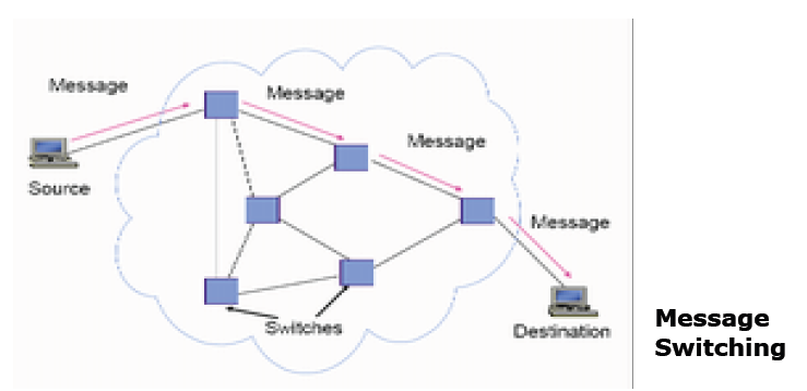
• In message switching, a message is
relayed from one switch to another until the message arrives at the destination
• A message switch operates in store
and forward fashion (a
message has to be completely received by the switch before it can be forwarded
to next switch)
• At the source each message has header
attached to it to provide source and destination address.
• CRC check bits
are attached to detect errors
• Each switch performs an error check, and
if no errors are detected, the switch examines the header to determine the next
hop in the path to the destination.
• Loss of messages may occur when a switch
has insufficient buffering to store the arriving message.
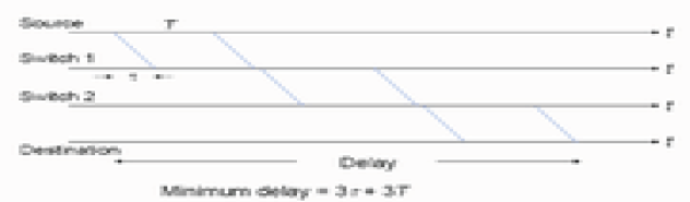
•above figure shows the minimum delay that
is incurred when a message is transmitted over a path that involves two
intermediate switches.
• The message has to traverse the link to
the first switch
• We assume
– the link has propagation delay in seconds,
T – the transmission time
• The message must traverse the link that
connect two switches and from second switch to the destination.
• It follows that the minimum delay is 3 +
3T
• In general, the delay incurred in message
switching involving L hops is L + LT
Disadvantages of message switching
• The probability of error increases with
the length of the block. Thus long messages are not desirable
• Not suitable for
interactive applications


0 comments