
Small signal analysis – fixed bias
• From the above re model,
Zi = [RB || βre] ohms
If RB > 10 βre, then,
[RB || βre] ~= βre
Then, Zi ~=re
• Zo is the output impedance when Vi =0. When Vi =0, ib =0, resulting in open circuit
equivalence for the current source.

• Zo = [RC|| ro ] ohms
• AV
– Vo = - βIb( RC || ro)
• From the re model, Ib = Vi / β re
• thus,
– Vo = - β (Vi / β re) ( RC || ro)
– AV = Vo / Vi = - ( RC || ro) / re
• If ro >10RC,
– AV = - ( RC / re)
• The negative sign in the gain expression indicates that there exists 180o phase
shift between the input and output.
Common Emitter - Voltage-Divider Configuration


• The re model is very similar to the fixed bias circuit except for RB is R1÷÷ R2 in the
case of voltage divider bias.
• Expression for AV remains the same.
Zi = R1 ÷÷ R2 ÷÷ b re
Zo = RC
• From the re model, Ib = Vi / b re
• thus,
Vo = - b (Vi / b re) ( RC || ro)
• AV = Vo / Vi = - ( RC || ro) / re
o If ro >10RC,
AV = - ( RC / re)
Common Emitter - Unbypassed Emitter-Bias Configuration


• Applying KVL to the input side:
Vi = Ib bre + IeRE
Vi = Ib bre +(b +1) IbRE
Input impedance looking into the network to the right of RB is
Zb = Vi / Ib = bre+ (b +1)RE
Since b>>1, (b +1) = b
Thus,
Zb = Vi / Ib = b (re+RE)
• Since RE is often much greater than re,
Zb = bRE,
•
Zi = RB||Zb
• Zo is determined by setting Vi to zero, Ib = 0 and b Ib can be replaced by open
circuit equivalent. The result is,
• Zo = RC
• AV : We know that, Vo = - IoRC
= - bIbRC
= - b(Vi/Zb)RC
AV = Vo / Vi = - b(RC/Zb)
Substituting, Zb = b(re + RE)
AV = Vo / Vi = - b[RC /(re + RE)]
RE >>re, AV = Vo / Vi = - b[RC /RE]
• Phase relation: The negative sign in the gain equation reveals a 180o phase shift
between input and output.
Emitter – follower
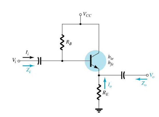

• Zi = RB || Zb
• Zb = bre+ (b +1)RE
• Zb = b(re+ RE)
• Since RE is often much greater than re, Zb = bRE
• To find Zo, it is required to find output equivalent circuit of the emitter follower
at its input terminal.
• This can be done by writing the equation for the current Ib.
Ib = Vi / Zb
Ie = (b +1)Ib
= (b +1) (Vi / Zb)
• We know that, Zb = bre+ (b +1)RE substituting this in the equation for Ie we get,
Ie = (b +1) (Vi / Zb)
= (b +1) (Vi / bre+ (b +1)RE )
Ie = Vi / [bre/ (b +1)] + RE
• Since (b +1) = b,
Ie = Vi / [re+ RE]
• Using the equation Ie = Vi / [re+ RE] , we can write the output equivalent circuit as,

• As per the equivalent circuit,
Zo = RE||re
• Since RE is typically much greater than re, Zo @ re
• AV – Voltage gain:
• Using voltage divider rule for the equivalent circuit,
Vo = Vi RE / (RE+ re)
AV = Vo / Vi = [RE / (RE+ re)]
• Since (RE+ re) @ RE,
AV @ [RE / (RE] @ 1
•
• Phase relationship
As seen in the gain equation, output and input are in phase.
Common base configuration
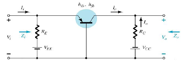
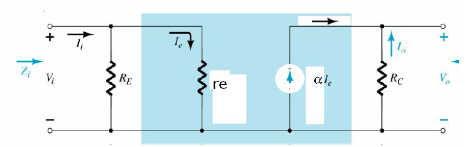
Small signal analysis
• Input Impedance: Zi = RE||re
• Output Impedance: Zo = RC
• To find, Output voltage,
Vo = - IoRC
Vo = - (-IC)RC = aIeRC
o Ie = Vi / re, substituting this in the above equation,
Vo = a (Vi / re) RC
Vo = a (Vi / re) RC
Voltage Gain: AV:
AV = Vo / Vi = a (RC/ re)
a @ 1; AV = (RC/ re)
Current gain
Ai = Io / Ii
Io = - a Ie = - a Ii
Io / Ii = - a @ -1
Phase relation: Output and input are in phase.


0 comments